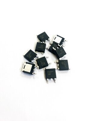
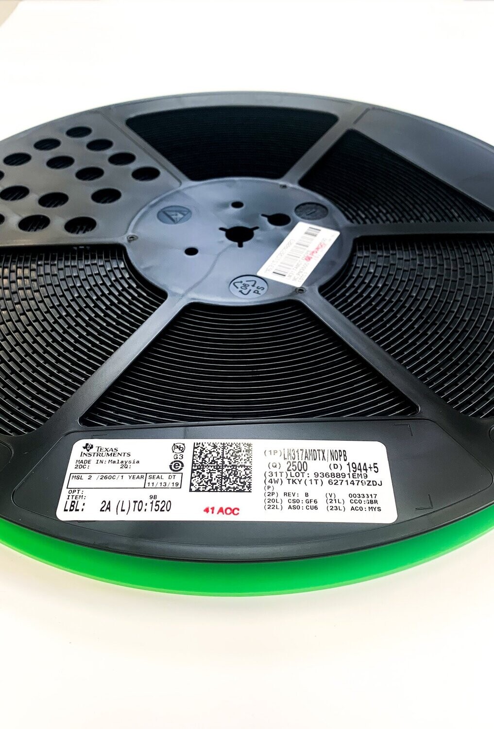
LM317A 1% Accurate 1.5A Adjustable Voltage Regulator
Deutsche Version
Absolute Maximum Ratings
| |
Min |
Max |
Einheit |
| Verlustleistung |
Intern begrenzt |
Intern begrenzt |
|
| Eingangs-/Ausgangsspannungsdifferenz |
−0.3 |
40 |
V |
| Lagertemperatur, T stg |
−65 |
150 |
°C |
Anmerkungen:
1. Belastungen, die über die unter Absolute Maximalwerte aufgeführten hinausgehen, können zu dauerhaften Schäden am Gerät führen. Dies sind nur Belastungswerte, die keinen funktionalen Betrieb des Geräts unter diesen oder anderen Bedingungen als den unter Empfohlene
Betriebsbedingungen. Wird das Gerät über einen längeren Zeitraum den Bedingungen der absoluten Maximalwerte ausgesetzt, kann dies die Zuverlässigkeit des Geräts beeinträchtigen.
2. Wenn für Militär/Luftfahrt spezifizierte Geräte benötigt werden, wenden Sie sich bitte an das Vertriebsbüro/den Vertrieb von Texas Instruments, um Verfügbarkeit und Spezifikationen zu erfahren.
ESD-Bewertungen
| |
|
|
Wert |
Einheit |
| V (ESD) |
Elektrostatische Entladung |
Menschliches Körpermodell |
±3000 |
V |
3. Eine Fertigung mit weniger als 500-V-HBM ist mit den notwendigen Vorkehrungen möglich. Pins, die als ±3000 V aufgeführt sind, können tatsächlich eine höhere Leistung haben.
Empfohlene Betriebsbedingungen
| |
Min |
Max |
Einheit |
| Betriebstemperatur |
-40 |
125 |
°C |
Thermische Informationen
| THERMISCH METRISCH |
LM317A, NDE (TO-220), 3 PINS |
LM317A, DCY (SOT-223), 4 PINS |
LM317, NDT (TO), 3 PINS |
LM317A, NDP (TO-252), 3 PINS |
3 PINS |
| R θJA , Übergangs-zu-Umgebung-Wärmewiderstand |
23.3 |
59.6 |
186 (3) |
54.0 |
°C/W |
| R θJC(top) , Übergangs-zu-Gehäuse (oben) Wärmewiderstand |
16.2 |
39.3 |
21 |
51.3 |
°C/W |
| R θJB , Übergangs-zu-Platine-Wärmewiderstand |
4.9 |
8.4 |
— |
28.6 |
°C/W |
| Ψ JT , Übergang-zu-Oberteil-Charakterisierungsparameter |
2.7 |
1.8 |
— |
3.9 |
°C/W |
| Ψ JB , Übergang-zu-Platine-Charakterisierungsparameter |
4.9 |
8.3 |
— |
28.1 |
°C/W |
| R θJC(bot) , Übergangs-zu-Gehäuse (unten) Wärmewiderstand |
1.1 |
— |
— |
0.9 |
°C/W |
Anmerkungen:
1. Weitere Informationen über traditionelle und neue thermische Metriken finden Sie im Anwendungsbericht "Semiconductor and IC package thermal metrics".
2. Wenn oberflächenmontierte Gehäuse verwendet werden (SOT-223, TO-252), kann der Übergangswiderstand zur Umgebung durch Vergrößerung der Leiterplatten-Kupferfläche, die thermisch mit dem Gehäuse verbunden ist, reduziert werden. Siehe Kühlkörperanforderungen für Kühlkörpertechniken.
3. Kein Kühlkörper
Elektrische Eigenschaften
Einige Spezifikationen gelten über den gesamten Betriebstemperaturbereich wie angegeben. Wenn nicht anders angegeben, T J = 25°C, V IN − V OUT = 5 V, und I OUT = 10 mA.
| PARAMETER |
MIN |
TYP |
MAX |
EINHEIT |
| Referenzspannung |
1.238 |
1.250 |
1.262 |
V |
| |
1.225 |
1.250 |
1.270 |
V |
| Netzregelung |
|
0.005 |
0.01 |
%/V |
| |
|
0.01 |
0.02 |
%/V |
| Lastregelung |
|
0.1% |
0.5% |
|
| |
|
0.3% |
1% |
|
| Thermische Regelung |
|
0.04 |
0.07 |
%/W |
| Abgleichstiftstrom |
|
50 |
100 |
μA |
| Änderung des Einstellstiftstroms |
|
0.2 |
5 |
μA |
| Temperaturstabilität |
|
1% |
|
|
| Minimaler Laststrom |
|
3.5 |
10 |
mA |
| RMS-Ausgangsrauschen, % von V OUT |
0.003% |
0.003% |
0.003% |
|
| Ripple-Unterdrückungsverhältnis |
|
65 |
|
dB |
| |
66 |
80 |
|
dB |
| Langzeitstabilität |
|
0.3% |
1% |
|
English version
Absolute Maximum Ratings
| |
Min |
Max |
Unit |
| Power dissipation |
Internally Limited |
Internally Limited |
|
| Input-output voltage differential |
−0.3 |
40 |
V |
| Storage temperature, T stg |
−65 |
150 |
°C |
Notes:
1. Stresses beyond those listed under Absolute Maximum Ratings may cause permanent damage to the device. These are stress ratings only, which do not imply functional operation of the device at these or any other conditions beyond those indicated under Recommended
Operating Conditions. Exposure to absolute-maximum-rated conditions for extended periods may affect device reliability.
2. If Military/Aerospace specified devices are required, please contact the Texas Instruments Sales Office/Distributors for availability and specifications
ESD Ratings
| |
|
|
Value |
Unit |
| V (ESD) |
Electrostatic discharge |
Human body model (HBM) |
±3000 |
V |
3. Manufacturing with less than 500-V HBM is possible with the necessary precautions. Pins listed as ±3000 V may actually have higher performance.
Recommended Operating Conditions
| |
Min |
Max |
Unit |
| Operating temperature |
-40 |
125 |
°C |
Thermal Information
| THERMAL METRIC |
LM317A, NDE (TO-220), 3 PINS |
LM317A, DCY (SOT-223), 4 PINS |
LM317, NDT (TO), 3 PINS |
LM317A, NDP (TO-252), 3 PINS |
3 PINS |
| R θJA , Junction-to-ambient thermal resistance |
23.3 |
59.6 |
186 (3) |
54.0 |
°C/W |
| R θJC(top) , Junction-to-case (top) thermal resistance |
16.2 |
39.3 |
21 |
51.3 |
°C/W |
| R θJB , Junction-to-board thermal resistance |
4.9 |
8.4 |
— |
28.6 |
°C/W |
| Ψ JT , Junction-to-top characterization parameter |
2.7 |
1.8 |
— |
3.9 |
°C/W |
| Ψ JB , Junction-to-board characterization parameter |
4.9 |
8.3 |
— |
28.1 |
°C/W |
| R θJC(bot) , Junction-to-case (bottom) thermal resistance |
1.1 |
— |
— |
0.9 |
°C/W |
Notes:
1. For more information about traditional and new thermal metrics, see the Semiconductor and IC package thermal metrics application report.
2. When surface mount packages are used (SOT-223, TO-252), the junction to ambient thermal resistance can be reduced by increasing the PCB copper area that is thermally connected to the package. See Heatsink Requirements for heatsink techniques.
3. No heatsink
Electrical Characteristics
Some specifications apply over full operating temperature range as noted. Unless otherwise specified, T J = 25°C, V IN − V OUT = 5 V, and I OUT = 10 mA.
| PARAMETER |
MIN |
TYP |
MAX |
UNIT |
| Reference voltage |
1.238 |
1.250 |
1.262 |
V |
| |
1.225 |
1.250 |
1.270 |
V |
| Line regulation |
|
0.005 |
0.01 |
%/V |
| |
|
0.01 |
0.02 |
%/V |
| Load regulation |
|
0.1% |
0.5% |
|
| |
|
0.3% |
1% |
|
| Thermal regulation |
|
0.04 |
0.07 |
%/W |
| Adjustment pin current |
|
50 |
100 |
μA |
| Adjustment pin current change |
|
0.2 |
5 |
μA |
| Temperature stability |
|
1% |
|
|
| Minimum load current |
|
3.5 |
10 |
mA |
| RMS output noise, % of V OUT |
0.003% |
0.003% |
0.003% |
|
| Ripple rejection ratio |
|
65 |
|
dB |
| |
66 |
80 |
|
dB |
| Long-term stability |
|
0.3% |
1% |
|


